Part 1: hardware connection
Prepare ACDP, OBP+ICP adapter, BCM interface board, and BCM module.
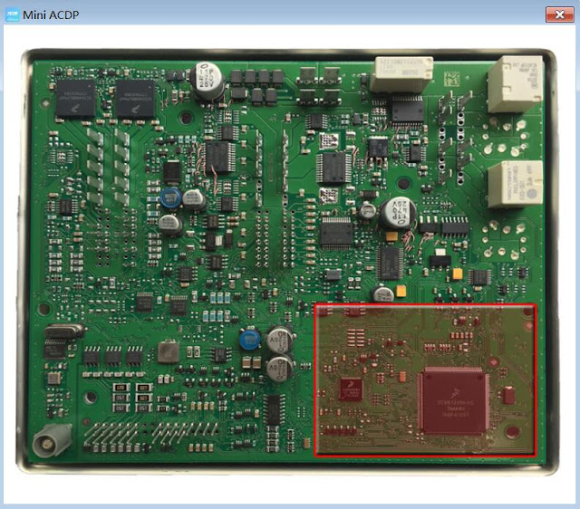
BCM module test point and positioning hole position area.
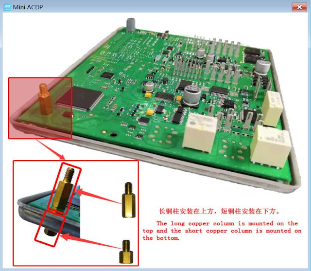
Install the copper pillar.
Aim the D1, D2, D3 and D4 positioning pin of the BCM interface board to the positions of D1, D2, D3 and D4 positioning hole on the BCM module.
BCM module test point location diagram: The figure above shows the ceramic packaged crystal oscillator diagram, the figure below shows the metal packaged crystal oscillator diagram.
Aim the BCM interface board positioning pin with the BCM module positioning hole and lock the copper pillar. The BCM interface board jumper cap short-circuited position is determined by using the crystal oscillator of the BCM module: EXT1 short-circuited for ceramic packaged crystal oscillator, EXT2 short-circuited for metal packaged crystal oscillator.
Connect ACDP device, OBP+ICP adapter, BCM interface board and BCM module.
Part 2: ACDP software operation
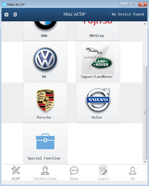
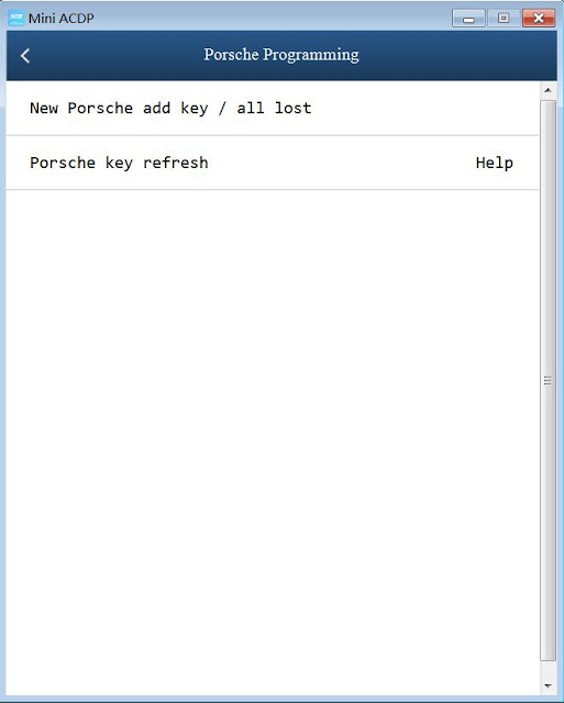
Open acdp software, click on "Porsche", then import "Read /write EEPROM / DFLASH" & "Read /write PFLASH" to achieve the purpose of cloning BCM.
http://blog.obd2shop.co.uk/how-to-clone-porsche-bcm-using-yanhua-acdp-module-10/


